
TM 5-3820-239-15
aligned with the pin. Refer to para-
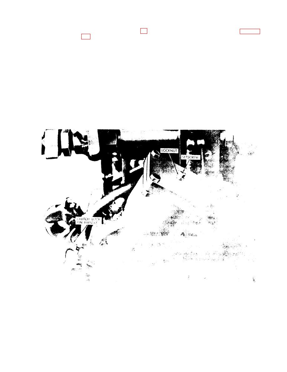
clockwise) the setscrew (fig. 2-2)
graph 2-5b for connections re-
on each brake cylinder. When the
quired.
setscrew is free of piston drag,
tighten the locknut to retain the
Warning: If the clutch lock pin
setting.
handle is engaged when air is di-
rected to the propelling air motors,
Caution: Be sure that the drill
the unit will move forward quick-
guide is raised high enough to
ly. Under no circumstances at-
clear obstacles.
tempt to pull the propelling motor
control handle back to cause re-
b. Connections.
verse tramming while standing
(1) Blow out the main air hose from the
near the clutch.
compressor, to assure that all foreign
(b) Set the propelling motor automatic
material is removed from the line. If
brakes by unscrewing (counter-
the hose is new, coat the inside sur-
Figure 2-2. Location of propelling air motor clutch handle and automatic brake
setscrew.
2-3

