
TM 5-3820-239-15
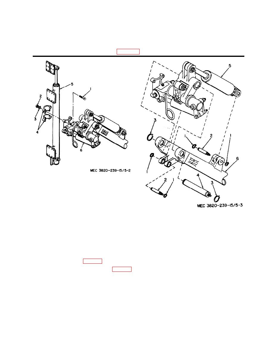
1 Bolt, hex-hd, 5/8-11 x 2 1/4 in. (14)
5 Drill guide extension cylinder mounting clamp (2)
2 Nut, hex, 5/8-11 (14)
6 Clamp shim (16)
3 Washer, lock, 5/8 in. (14)
7 Complete drill mounting
4 Drill guide mounting plate clamp (4)
Figure 5-1-Continued.
1 Guide mounting swivel cap bolt, 7/8-9 x 5 in.
(4).
2 Nut, hex, 7/8-9 (4)
3 Washer, lock, 7/8 in. (4)
4 Guide mounting swivel cap (2)
5 Power guide extension mounting
6 Power dump and swing assembly
1 Retaining ring (4)
Figure 5-2. Removal and installation of power guide
2 Dump oin (2)
extension mounting.
3 Retaining ring (2)
4 Dimp pivot pin
drain adapter under the main frame,
5 Power dump and swing assembly
and. remove magnetic plug (2) and
6 Hydraulic boom assembly
gasket (3), allowing the hydraulic
reservoir to empty.
Figure 5-3. Removal and installation of power dump
and swing assembly.
(2) Disconnect the hydraulic fittings at
the suction oil filter and the return
(4) Using a suitable hoist, carefully lift
line oil filter (fig. 1-5).
the boom base assembly (8) from the
main frame (9), being careful not to
(3) Remove the two screws (4, fig. 5-5)
damage the protruding hydraulic
and lock washers (7) from the tapped
drain adapter.
holes in the main frame (9), and re-
Note. If may be desirable to remove
move the three screws (5), nuts (6),
the hydraulic drain adapter, nipple, and
and lock washers (7) from the re-
elbow from the bottom of the boom base
maining three holes in the boom base
assembly before attempting to lift the as-
assembly (8) and main frame.
sembly.
5-5

