
TM 5-3820-241-34
b. Disassembly.
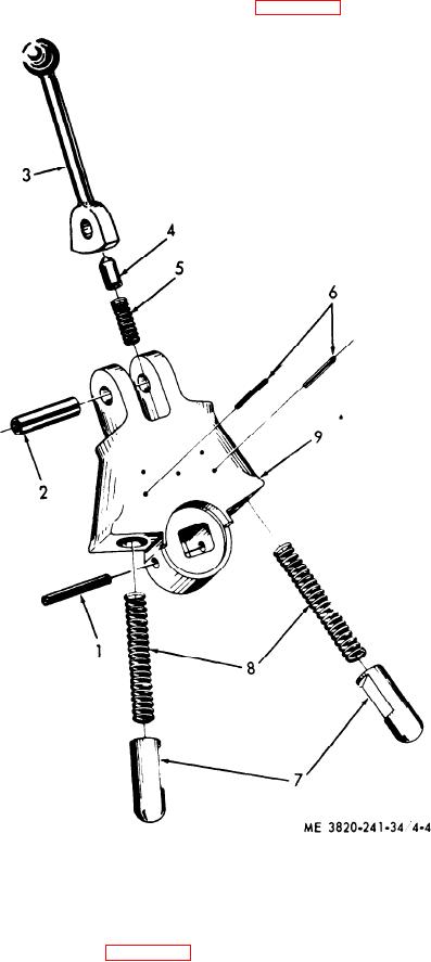
components in numerical sequence as illustrated
(1) Disassemble the tramming valve handle
in figure 4-4.
4 Plunger
7 Plunger
1 Spring pin
2 Spring pin
5 Plunger spring
8 Plunger spring
3 Control handle
6 Spring pin
9 Control body
Figure 4-4. Tramming throttle valve handle. disassembly and reassembly.
(2) Disassemble the tramming throttle valve
in numerical sequence as illustrated in figure 4-5.

