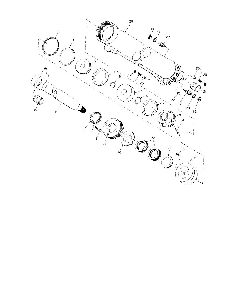
Page G-47. Figure 6-20.1 is added.
ME 3820-239.15/6-20.1 C2
1
Capscrew
11 O-ring
21 Bushing
2
Lockwasher
12 V-packing
22 Pipe plug
3
Lock pin
13 Male adapter
23 Pipe plug
4
Rear backing plate
14 Spring
24 Spring
5
U-cup
15 Cylinder head
25 Poppet
6
O-ring
16 Gland nut
26 Pipe plug
7
Piston
17 Retainer ring
27 Pilot check piston
8
0-ring
18 Rod wiper
28 Piston ring
9
Front backing plate
19 Piston rod assembly
29 Barrel assembly
10
Backup ring
20 Lubrication fitting
Figure 6-20.1. Typical hydraulic cylinder, exploded view.


