TM 5-3820-241-34
Section III. DRIFTER DRILL
5-9. General
a. Description. The pneumatic drill engine is a
heavy duty percussion machine designed for deep
hole drilling in hard rock. The drill incorporates a
dual rotation assist unit integral with the drill to
provide a fast method for coupling and un-
coupling the drill steels, and to furnish a power
assist to normal rifle bar rotation. The dual
rotation unit consists of an independent vane type
air motor geared to rotate the chuck in either
direction. Operating controls for the drill and
allied functions are mounted on the feed.
b. Theory of Operation. There are two basic
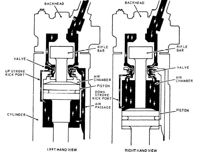
Figure 5-5. Drifter drill valve operation.
operating principles involved in the action of the
drill engine. First, the principle that makes the
piston reciprocate in the cylinder, and second, the
principle that causes the drill steel to rotate.
(1) Piston Reciprocation. Back and forth
movement of the piston is affected by a self-
acting or automatic valve that admits air at the
proper instant, first to one end of the cylinder
then to the other end. Figure 5-5 illustrates the
involved portion of the drill engine in cross
section. The left hand view shows the piston at
the top part of the cycle, and in the right hand
view, the piston is in the bottom part of the cycle.
ME 3820-241-34/5-5
(2) Value Operation.
In figure 5-5 (left hand
view) the piston is shown moving to the up-
permost part of the cycle. Just before it reaches
the top of the chamber it uncovers the air kick
port that allows air to flow through the kick port
to the backside of the valve. This pressure causes
the valve to close the air supply to the back end of
the cylinder and to admit air to the front end
5-7


