
TM 5-3820-241-34
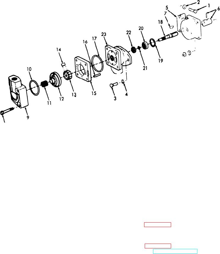
8
ME 3820-241-34/3-12
1
Hex head capscrew
7
Drive shaft key
13.
Pump rotor
19
Snap ring
2
Lockwasher
8
Cover mounting screw
14
Rotor vane
20
Shaft bearing
3
Hex head capscrew
9
Pump cover
15
Ring
21
Snap ring
4
Lockwasher
10
O-ring
16
Straight pin
22
seal
5
Pump mounting bracket
11
Spring
17
O-ring
33
Pump body
6
Pump coupling
12
Pressure plate
18
Pump shaft
Figure 3-12. Hydraulic pump and drive coupling. disassembly and reassembly.
(5) Inspect the pump shaft keyway and key
3-19. Hydraulic Pump and Drive Coupling,
for damage or excessive wear.
Cleaning Inspection and Repair
(6) Inspect all hardware and threaded areas
a. Cleaning.
for damage. Replace defective hardware.
(1) Clean all parts except O-rings in cleaning
(7) Repair by replacement of all defective
solvent (Fed Spec PD 680) and dry thoroughly.
parts.
(2) Discard and replace all O-rings.
b. Inspection and Repair.
3 - 2 0 . Hydraulic Pump and Drive Coupling,
(1) Inspect shaft bearing for excessive wear,
Reassembly and Installation
roughness or binding while rolling on shaft.
a. Reassembly. Reassemble the hydraulic
(2) Inspect rotor vanes for chips and ex-
pump in the reverse of disassembly sequence as
cessive wear. If any vane is defective, replace
illustrated in figure 3-12.
them all with a rotor repair kit.
b. Installation.
(3) Inspect the rotor for cracks, scores and
(1) Install the hydraulic pump and drive
rough spots. Remove minor rough spots with
coupling in the reverse of numerical sequence as
emery cloth. Replace a badly worn rotor.
illustrated in figure 3-11.
(4) Inspect the pump housing and covers for
(2) Refer to LO 5-3820-241-12 and service
cracks, nicks and burrs on machined surfaces.
the hydraulic reservoir.
Remove small nicks with a fine emery cloth.

