TM 5-2590-512-13&P
SECTION V. UNIT MAINTENANCE PROCEDURE
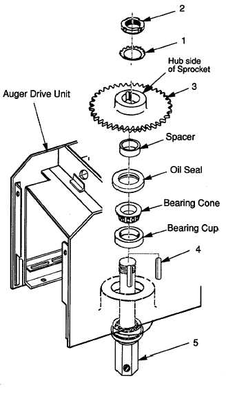
4-25. Driven Sprocket Replacement.
This task covers:
a. Removal
b. Installation
Initial Setup
Tools:
Equipment Conditions:
General Mechanic's Tool Kit
Chain Removed (para 4-20).
5180-00-177-7033
Materials and Parts:
None.
a. Removal.
1.
Straighten the tangs on lock washer (1).
2.
Remove lock nut (2) and lock washer (1).
NOTE
Use a spanner wrench to remove
lock nut (2)
3.
Support
output
shaft
(5)
to
prevent
movement while carefully sliding off driven
sprocket (3) and shaft key (4)
NOTE`
Use care in removing driven sprocket
to avoid damage to shaft threads.
b. Installation.
1.
Install shaft key (4) in slot in output shaft (5)
and slide replacement driven sprocket (3)
(with hub side up) onto shaft (5). Use care
to avoid damaging threads.
2.
Install lock washer (1) and lock nut (2).
Finger tighten lock nut (2). Do not bend
tangs on lock washer (1) at this time.
FOLLOW ON TASKS:
Shaft bearing adjustment (see para 4-27).
Install chain (see para 4-20).
END OF TASK
4-26


