
TM 5-3820-241-34
b. Disassembly.
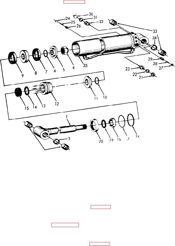
(1) Disassemble the boom swing cylinder in
numerical sequence as illustrated in figure 3-8.
ME 3820-241-34/3-8
2
19
Wiper rod
1
Piston rod assembly
28
Spring
10
O-ring
20
Ring retainer
29
Poppet
2
Piston rod bushing
11
Backing plate
21
Pipe plug
30
Pipe plug
12
Cylinder head
3
Piston rod spacer
31
Piston ring
13
Spring
22
Piston ring
4
Lock nut
32
Pilot check piston
23
Pilot check piston
14
Male adapter
5
Backing plate
33
Barrel bushing
24
Pipe plug
15
V-packing
6
O-ring
34
Barrel spacer
25
Spring
16
O-ring
7
U-cup
35
Barrel assembly
26
Poppet
17
Back up ring
8
Piston
27
Pipe plug
18
Gland nut
9
U-cup
Figure 3-8. Boom swing cylinder, disassembly and reassembly.
(2) Use a s u i t a b l e d r i f t a n d d r i v e o u t
the reverse of numerical sequence as illustrated in
bushings (2) and (33) and spacers (3) and (34).
3-12. Boom Swing Cylinder Cleaning, Inspection
(2) Align the holes in spacers (3) and (34)
and Repair
with holes in piston rod (1) and barrel assembly
Clean, inspect and repair the boom swing cylinder
(35). Lubricate and press spacers (3) and (34) and
in a similar manner as outlined in paragraph 3-3.
bushings (2) and (33) into position.
b. Installation.
3-13. Boom Swing Cylinder, Reassembly and
(1) Install the boom swing cylinder in the
Installation
reverse of numerical sequence as illustrated in
a. Reassembly.
(1) Reassemble the boom swing cylinder in