
TM 5-3820-241-34
ME 3820-241-34/5-4
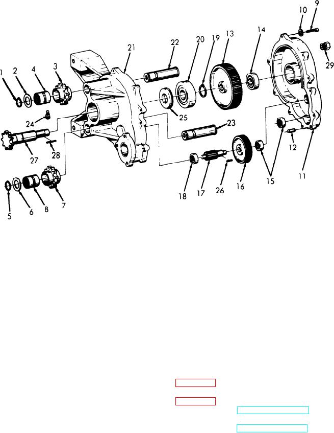
22
Idler gear shaft
15 Ball bearing
8 Roller bearing
1
Snap ring
23
Idler gear shaft
16 Spur gear
9 Hex head capscrew
2
Sprocket washer
24
Lubrication'fitting
17 Spur gear
10 Lockwasher
3
Sprocket idler
25
Shield
16 Ball bearing
11 Transmission cover
4
Roller bearing
26
Gear to shaft key
19 Snap ring
12 Dowel pin
5
Snap ring
27
Drive sprocket
20 Ball bearing
13 Main drive gear
6
Sprocket washer
28
Drive sprocket key
21 Transmission housing
14 Ball bearing
7
Sprocket idler
29 Vented plug
Figure 5-4. Feed transmission, disassembly and reassembly.
5-8. Feed Transmission, Reassembly and In-
5-7. Feed Transmission, Cleaning, Inspection and
stallation
Repair
a. Reassembly.
a . Cleaning. Clean all parts with cleaning
(1) Lubricate all components with a light
solvent (Fed Spec PD 680) and dry thoroughly.
weight engine oil.
b. Inspection and Repair.
(2) Reassemble the feed transmission in the
(1) Inspect all gears for cracks, chipped teeth
reverse of numerical sequence as illustrated in
or excessive wear.
(2) Inspect the bearings for rough spots or
b. Install the feed transmission as illustrated in
excessive wear.
( 3 ) Inspect the transmission cover and
(2) Refer to TM 5-3820-241-12 and install the
housing for cracks, breaks or other damage.
feed motor and feed chain.
(4) Inspect the idler gear shafts for excessive
(3) Refer to LO 5-3820-241-12 and service the
wear.
feed transmission.
(5) Inspect shaft keys and keyway in shafts
for excessive wear.
(6) Repair by replacement of defective parts.
5-6