TM 5-3820-241-34
b. Disassembly.
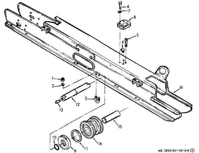
(1) Disassemble the crawler side frame in
numerical sequence as illustrated in figure 6-6.
1 Plain hex nut
5 Pressure relief screw
9 Thrust washer
13 Lubrication fitting
2 Lockwasher
6 Hex head capscrew
10 O-ring
14 Track roller
3 Roller shaft U-bolt
7 Lockwasher
11 Oil seal
15 Bronze bearings
4 Lubrication fitting
8 Roller cap
12 Roller shaft
16 Side frame weldment
Figure 6-6. Crawler side frame, disassembly and reassembly (sheet 1 of 2).
6-11

