
TM 5-3820-239-15
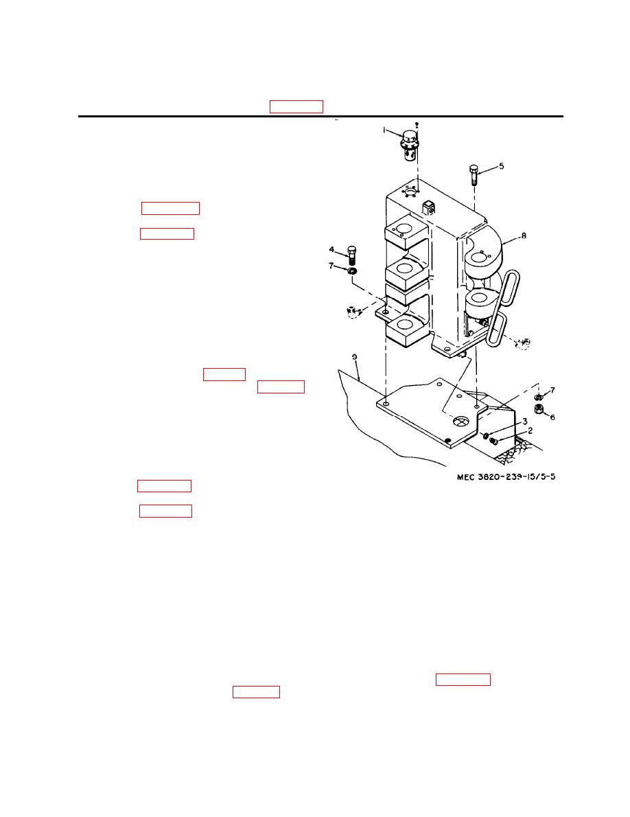
4 King pin locking plate (8)
1 Screw, cap, hex-hd, 1/2-13 x 1 in. (4)
5 Hydraulic boom assembly
2 Screw, cap, hex-hd, 1/2-13 x 1 1/2 in. (2)
6 Boom base assembly
3 Washer, lock, 1/2 in. (6)
Figure 5-4-Continued.
b. Installation.
Note. Before installing the boom base assembly,
clean and flush the hydraulic reservoir, clean the suc-
tion oil filter and magnetic plug, and replace the re-
turn line oil filter as described in Chapter 3, Section
IV.
(1) See figure 5-5 and install the boom
base assembly.
(2) See figure 1-5 and make all hydraulic
connections required.
a. Removal.
Note. The procedure for both complete traction
drives is identical. Only the orientation is different.
The following procedure and illustrations cover only
the left (roadside) traction drive.
(1) Disconnect the air piping fittings at
the traction drive, propelling air mo-
tor, and brake (fig. 1-3).
(2) Remove the six nuts (1, fig. 5-6),
and lock washers (2) from the hous-
ing flange of traction unit (6).
(3) Slide complete traction drive (4),
with studs (3) attached, out of the
traction unit housing and the mount-
ing holes in the main frame.
b. Installation.
(1) See figure 5-6 and install the com-
Vent cap
1
2
Magnetick drain plug, 3/4-16
plete traction drive.
Gasket
3
(2) See figure 1-3 and make all air pip-
Scxrew, cap, hed-hd, 1-8 x 2 1/4 in. (2)
4
ing connections required.
Screw, cap, hes-hd, 1-8 x 3 1/4 in. (3)
5
6
Nut hex, 1-8 (3)
7
Washer, lock 1 in. (5)
8
Boom base assembly
a. General. The auxiliary items for the pneu-
Main fram
9
matic drill consist of the tool box, the tools
Figure 5-5. Removal and installation of boom base
provided in the box, drill shank pieces, and
assembly.
instruction and identification plates.
(11), and lock washers (12), and re-
b. Removal.. Normally removal is required
move the tool box from the frame.
only if parts are damaged. The only items re-
(2) To remove damaged plates, remove
quiring removal are the tool box and instruc-
the four drive screws (1) holding the
tion and identification plates.
plate.
(1) To remove the tool box, open the lid
and remove any tools within the box.
auxiliary items.
Remove screws (10, fig. 5-7), nuts

