Section V. MAINTENANCE OF HYDRAULIC SYSTEM
3-10.
General
The rock drill hydraulic system consists of a hydraulic
pump, pump drive motor, pressure regulator, control
valve, reservoir, lift boom, swing, tilt, and extension
cylinders, and the necessary hoses and fittings. Refer to
figure 1-5 for a hydraulic system schematic diagram.
3-11.
Hydraulic Hoses
a.
Inspect the hydraulic hoses and fittings for
cracks, breaks or leaks. Presence of hydraulic fluid on
any of components or under the crawler indicates loose
fittings or damaged hoses.
b.
Check and tighten loose hydraulic fittings or
hose.
c.
Report
defective
hoses
to
organizational
maintenance.
3-12.
Hydraulic Pump and Drive Motor
a.
Inspect the hydraulic pump and drive motor for
secure mounting and leaks at the inlet and outlet fittings.
b.
Tighten all loose mounting hardware and fittings.
3-13.
Hydraulic Air Pressure Regulator
a.
Inspection. Inspect the pressure regulator for
secure mounting. Inspect the hydraulic and air hoses to
the regulator for secure mounting. Tighten all loose
mounting hardware of hoses.
b.
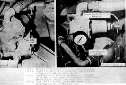
Adjustment. Adjust the air pressure regulator as
illustrated in figure 3-2.
Figure 3-2. Air pressure regulator adjustment
3-14.
Hydraulic Control Valve
Make a periodic inspection of the hydraulic control valve
to see that all hose connections and mounting hardware
are secure. Inspect hoses for ruptures or other damage.
3-15.
Hydraulic Cylinders
a.
The rock drill is equipped with {5 cylinders
consisting of lift, swing, tilt, extension and boom
cylinders.
b.
Check to make sure that all cylinders extend and
3-5


