
TM 5-3820-241-34
the reverse of numerical sequence as illustrated in
nicks, and burrs. Remove small nicks with a fine
figure 3-15.
emery cloth.
b. Installation. Refer to TM 5-3820-241-12
(5) Inspect all hardware and threaded areas
and install the air motor.
for damage. Replace defective hardware retap
threaded areas or replace defective part.
4-4. Air Motor, Reassembly and Installation
a. Reassembly. Reassemble the air motor in
Section II. AIR PRESSURE REGULATOR
4-7. Air Pressure Regulator Cleaning, Inspection
4-5. General
and Repair
The air pressure regulator is an adjustable spring
a. Cleaning.
diaphragm type control that regulates the
(1) Clean all p a r t s except O-rings and
amount of air supplied to the hydraulic pump aid
diaphragm assembly in cleaning solvent (Fed
drive motor. It is mounted just above the air
Spec PD 680) and dry thoroughly.
motor and is normally set at 65 psi.
(2) Discard and replace all O-rings and the
4-6. Air Pressure Regulator, Removal and
diaphragm assembly.
Disassembly
b. Inspection and Repair.
a. Removal. Refer to TM 5-3820-241-12 and
(1) Inspect the valve and valve seat for
remove the air pressure regulator.
excessive wear or other damage.
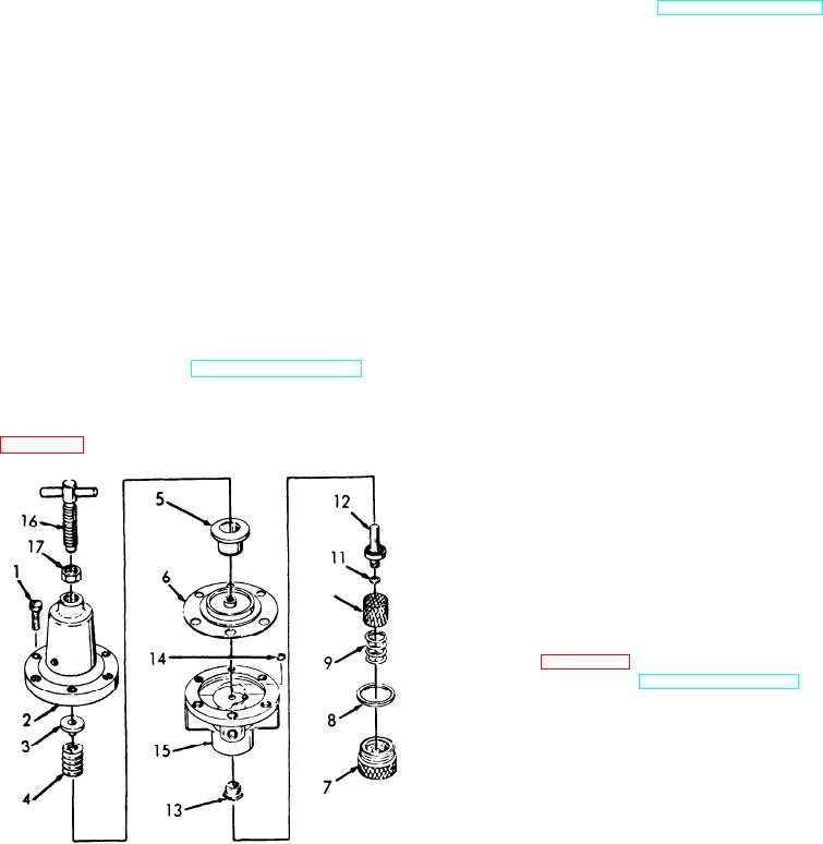
b. Disassembly. Disassemble the air pressure
(2) Inspect the strainer for holes or signs of
regulator in numerical sequence as illustrated in
excessive strain.
NOTE
Most pressure regulator failures can be
corrected by the installation of a new
d i a p h r a g m assembly, O-rings, valve
strainer and springs.
(3) Repair by replacement of defective parts.
4-8. Air Pressure Regulator, Reassembly and
Installation
a. Reassembly. Reassemble the air pressure
regulator in the reverse of numerical sequence as
illustrated in figure 4-2.
b. Installation. Refer to TM 5-3820-241-12 and
install the air pressure regulator.
ME 3820-241-34/4-2
9 Spring
1
Bonnet set screw
10 Air strainer
2
Bonnet
3
Spring rest
11 O-ring
12 Valve
4
Bonnet spring
5
Diaphragm rest
13 Valve seat
14 O-ring
6
Diaphragm assembly
15 Bonnet boot
7
Plug
16 Adjusting screw
8
O-ring
17 Locknut
Figure 4-2. Air pressure regulator. disassembly and reassembly.