
TM 5-3820-241-34
(4) Replace all defective parts.
4-11. Tramming Motor Throttle Control Valve,
Cleaning, Inspection and Repair
4-12. Tramming M o t o r T h r o t t l e V a l v e ,
Reassembly and Installation
a. Cleaning. Clean all- parts with cleaning
solvent (Fed Spec PD 680) and dry thoroughly
a. Reassembly.
b. Inspection and Repair.
(1) Reassemble the tramming throttle valve
(1) Inspect the control handle plungers for
in the reverse of numerical sequence as illustrated
s c r a t c h e s or excessive wear, r e m o v e minor
in figure 4-5.
scratches with a fine emery cloth.
(2) Reassemble the tramming valve handle
(2) Inspect the plunger springs for breaks or
components in the reverse of numerical sequence
excessive wear.
as illustrated in figure 4-4.
(3) Inspect the valve body, valve and
b. Installation. Install the tramming motor
compression rings for nicks, cracks, or burrs.
throttle control valve in the reverse of numerical
P o l i s h minor nicks or scratches with a fine
sequence as illustrated in figure 4-3.
a b r a s i v e cloth. Replace compression rings if
cracked or chipped.
Section IV. LUBRICATOR FITTING
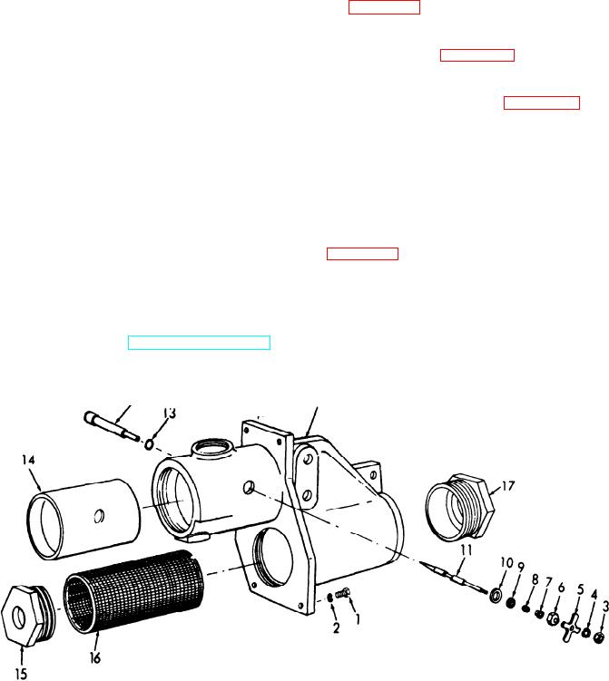
b. Disassembly. Disassemble the lubricator
4-13. General
fitting in numerical sequence as illustrated in
The lubricator
fitting, mounted at the rear center
of pneumatic
rock drill is an adjustable fitting
that filters the
air and controls the amount of air
and oil that is
introduced into the air system.
4-14. Lubricator Fitting Removal and Dis-
assembly
a. Removal. Refer to TM 5-3820-241-12 and
remove the lubricator fitting.
ME 3820-241-34/4-6
1 Hex head capscrew
7 Stem follower
13 O-ring
2 Lockwasher
8 Stem packing
14 Oiler bushing
9 Stem washer
3 Hex nut
15 Pipe hushing
4 Lockwasher
10 Stem seal
16 Oiler screen
5 Adjusting handle
11 Stem
17 Reducing bushing
6 Plain hex nut
18 Lubricator body
12 Valve body
Figure 4-6. Lubricator fitting, diassembly and reassembly.