
TM 5-3820-241-34
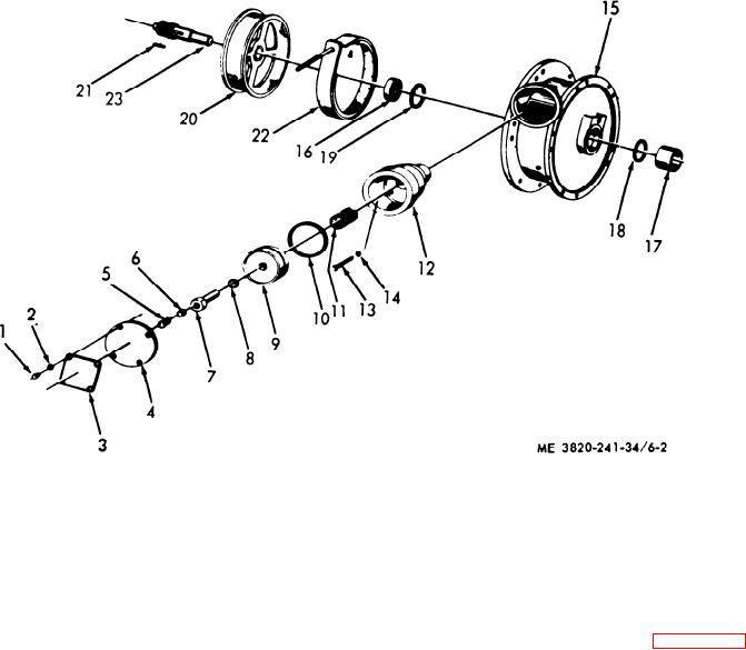
13 Hex head capscrew
19 Hearing retaining ring
7 Adjusting nut
1
Hex head capscrew
20 Bearing retaining ring
8 O-ring
14 Lockwasher
2
Lockwasher
9 Piston
15 Gear and brake housing 21 Brake band assembly
3
Name plate
22 Brake drum
10 Piston O-ring
16 Breather vent plug
4
Air motor cover
17 Housing bearing
23 Brake drum shaft
11 Spring
5
Pipe plug
24 Brake drum shaft key
6
Set screw
12 Cylinder head
18 Housing bearing
Figure 6-2. Tramming transmission, brake, disassembly and reassembly
(a) Disassemble the tramming trans-
(b) To remove the brake band (21) from
mission gear case, a n d the carrier gears in
the brake (22), expand the brake band sufficiently
numerical sequence as illustrated in figure 6-3.
to clear the flange on the brake drum.
(2) Tramming Transmission.