• Home
  • Download PDF
  • Order CD-ROM
  • Order in Print
Figure 6-5. Equilizer arm and bar, removal and installation (Sheet 2 of 2)
Figure 6-6. Crawler side frame, disassembly and reassembly (sheet 2 of 2).

Maintenance Manual Drill, Pneumatic Drifter; Boom-Type, Crawler Mounted, Self-Propelled Page Navigation
  75    76    77    78    79  80  81    82    83    84    85  
img
. . .
TM 5-3820-241-34
b. Disassembly.
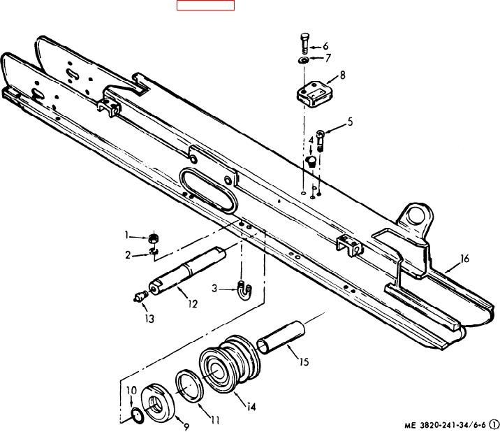
(1) Disassemble the crawler side frame in
numerical sequence as illustrated in figure 6-6.
1
Plain hex nut
5
Pressure relief screw
9
Thrust washer
13 Lubrication fitting
2
Lockwasher
6
Hex head capscrew
10
O-ring
14 Track roller
3
Roller shaft U-bolt
7
Lockwasher
11
Oil seal
15 Bronze bearings
4
Lubrication fitting
8
Roller cap
12
Roller shaft
16 Side frame weldment
Figure 6-6. Crawler side frame, disassembly and reassembly (sheet 1 of 2).
6-11


Privacy Statement
Press Release
Contact

© Copyright Integrated Publishing, Inc.. All Rights Reserved.