TM 5-3820-241-34
ME 3820-241-34/5-10
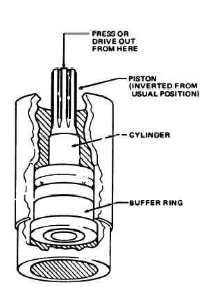
Figure 5-10. Removing buffer ring assembly.
5-11. Drifter Drill Cleaning, Inspection and
Repair
a. General. The drill engine should be
disassembled for cleaning and inspection at
regular intervals, short of time when breakdown
may occur.
Because of varied operation con-
ditions, inspection periods cannot be determined.
They can only be arrived at with accumulated
experience of the user, until safe cleaning and
inspection intervals can be established. Drills in
daily service must be returned to direct and
general support maintenance for disassembly,
inspection and repair as required. In addition a
routine inspection for signs of excessive wear,
scoring, broken or cracked parts must be made.
b. Cleaning.
(1) Clean all
parts except O-rings with
cleaning solvent (Fed Spec PD 680) and dry
thoroughly.
(2) Discard and replace all O-rings and seals.
c. Inspection and Repair.
(1) Buffer R ing Cylinder and Piston.
(a) The most frequent reason for poor drill
performance is that the piston, cylinder or buffer
ring lining have worn to such an extent that the
clearance between then has increased beyond the
allowable wear
limits.
Excessive clearance
destroys the air cushion between the buffer ring
and piston, and allows the piston to strike the
buffer ring with considerable impact, and often
breaking the the piston.
(b) Check the piston, cylinder, or buffer
ring for excessive wear by applying the cushion
test. This is accomplished by dropping the free
piston in the cylinder. The piston should bounce
or cushion on the air trapped between the piston
head and buffer ring. If the piston strikes the
buffer ring hard, the piston, cylinder lining or
buffer ring is defective and worn beyond safe
limits and they must be replaced.
(2) Piston Striking Face.
(a) Inspect the piston striking face to
make sure it is not chipped or cupped excessively.
A defective piston will damage every striking bar
with which it comes in contact.
A stripped or
damaged striking bar will quickly spoil a good
piston.
(b) If the piston striking face damage has
not progressed so far, it can be repaired. If the
piston has never been reground, the striking face
must be squared up and flattened by careful
grinding. Perform the grinding operation slowly
to avoid overheating and annealing of the hard-
ened cast. Do not grind off more than 1/16-in. of
metal.
(3) Rifle Nut and Chuck.
(a) Inspect the raffle bar for a good fit in
the rifle nut, allowable wear depends to some
extent on drilling conditions. Lock the rifle nut
when you can slide a 1/8-in. shim between the
flutes when these parts are engaged.
(b) Inspect the splines in the chuck nut for
excessive wear. The piston bears on the splines in
the chuck nut in the direction of rotation only, so
more nut wear can be tolerated. Replace the chuck
nut if wear exceeds 1/2 the thickness of the
splines.
(4) Chuck Parts.
(a) Inspect the chuck and chuck bushing
for excessive wear. When the chuck or bushing is
worn, alignment of the drill with the striking bar
cannot be maintained. It will also cause chipping
of the piston or striking bar and may shear off or
punch the air tube.
(b) Replace a
chuck bushing if worn
oversize or bell-mounted.
(5) Motor Vanes.
(a) Inspect the motor vanes for excessive
wear. If the laminations show any sign of
separating, discard and replace with an complete
new set.
(b) Inspect the sides of the vanes for
indication of excessive milling. When a maximum
of 1/8-in. of the original vane width is worn away,
5-15


