TM 5-3820-241-34
(a) Insert shaft (fig. 5-11) through
opening, through the torque compensator gear
and into cap.
(b) Turn shaft until pin dowels into the
hole in the cap. Install spring, cover and secure
with four lockwashers and capscrews.
(c) Assemble needle bearings into motor
bearing support. Install motor bearing support
into housing, align support and housing and
install aligning pin.
(d) Install vanes in rotor, assemble needle
bearing on rotor, and install the rotor in the
housing. Make sure the seal in back cover is in
place and install back cover on the housing and
secure with four nuts.
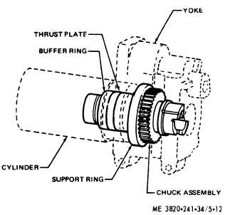
(5) To assemble the chuck parts refer to
figure 5-12 and proceed as follows:
(a) Assemble the support ring (fig. 5-12)
to the chuck. Install this assembly into the yoke
and tap into place until the support ring shoulders
in the housing. Install buffer ring in the cylinder.
(b) Position
t h e t h r u s t p l a t e i n
the
cylinder against the buffer ring. Position cylinder
in yoke (exhaust port towards the cradles) and
tap lightly until cylinder bottoms on yoke.
(6) Reassemble the piston, valve and
rotation parts as follows:
(a) Position the piston (41, fig. 5-8), in the
cylinder assembly (39), with flutes on piston
entered in slots on chuck nut.
(b) Hold locating pin (30) in the groove in
the cylinder assembly (39), line up slots in the
valve seat assembly (34) and valve block (33) with
locating pin (30) and assemble the valve into the
cylinder assembly (39). Tap into position until the
valve assembly seats on the cylinder lining.
(c) Install pawl spring (25). pawl plunger
(24) and pawls (23) into rifle bar (21).
(d) Install the rifle bar flutes into the rifle
nut (42) and install rotation release ring (20), into
ratchet ring (26). Line up ratchet ring with
locating pin (19) and tap into position against the
valve cover. Install support ring (27).
(7) Tighten
n u t s ( 9 ) a l t e r n a t e l y a n d
uniformly to 125 ft. lb. torque.
b. Installation.
(1) Install
th e drifter drill assembly in
reverse of numerical sequence as illustrated in
figure 5-7.
(2) Refer to LO 5-3820-241-12 and service
the rock drill.
Figure 5-12. Reassembly of chuck assembly.
Section IV. DRILL AND FEED CONTROL VALVE
5-13. General
The drill and feed control valve controls the drill
feed, blow, and rotation functions and is mounted
on the front end of the feed assembly.
5-14. Drill and Feed Control Valve, Removal and
Disassembly
b. Disassembly. Disassemble the drill and feed
control valve
in disassembly sequence as
illustrated in fig. 5-13.
a. Removal. Refer to TM 5-3820-241-12 ane
remove the drill and feed control valve.
5-17


