7-6.
Feed Motor Repair
a. Disassembly.
(1) Remove hoses and fittings from feed motor
(see TM 5-3820-241-12).
NOTE
Scribe feed motor and quill motor flange to en-
sure proper reassembly.
(2)
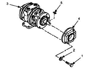
Remove four screws (1) and lockwashers (2) se-
curing feed motor (3) to quill motor flange (4). Remove
feed motor and key (5). Discard lockwashers.
(3)
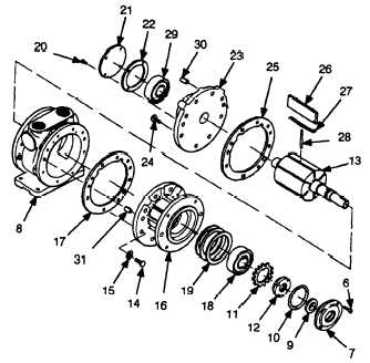
Remove four screws (6). Remove drive end cap
(7) from body (8).
(4)
Remove and discard seal (9) and O-ring (10).
(5)
Open tabs on lockwasher (11). Remove locknut
(12) and lockwasher from rotor (13).
(6)
Remove eight screws (14) and lockwashers (15).
Remove drive end plate (16) and gasket (17) from body (8).
Discard lockwashers and gasket.
(7)
Remove bearing (18) and spacers (19) from in-
side drive end plate (16).
(8) Remove four screws (20). Remove dead end
cap (21) and gasket (22) from dead end plate (23). Discard
gasket.
(9)
Remove eight screws (24). Remove dead end
plate (23), gasket (25), and rotor (13) from body (8). Vanes
(26) and springs (27) will come off as rotor is removed. Dis-
card gasket.
(10) Remove three push pins (28) from rotor (13).
(11) Press bearing (29) and rotor (13) out of dead
end plate (23).
(12) If damaged, remove two dowel pins (30) from
dead end plate (23).
(13) If damaged, remove two dowel pins (31) from
drive end plate (16).
b. Inspection.
(1)
TM 9-214.
Clean and inspect bearings in accordance with
(2)
Inspect all parts for cracks, damage, and exces-
sive wear. Replace all damaged and worn parts.
c. Assembly.
(1)
If removed, install two dowel pins (31) in drive
end plate (16).
(2)
If removed, install two dowel pins (30) in dead
end plate (23).
(3)
Install rotor (13) in drive end plate (16).
(4)
(13).
Install spacers (19) and bearing (18) over rotor
(5)
Install lockwasher (11) and locknut (12) over
rotor. Ensure that tab on lockwasher engages rotor shaft.
CAUTION
Do not fully tighten locknut. Rotor must turn
freely.
.
(6)
Tighten locknut (12), then bend tabs on lock-
washer (11) over locknut.
(7)
Install new seal (9) in drive end cap (7).
(8)
Install drive end cap (7) and new O-ring (10) on
drive end plate (16) using four screws (6).
(9)
Install three push pins (28) in rotor (13).
(10) Install six springs (27) and vanes (26) in rotor
(13). Install vanes with notches to front of feed motor.
(11) Compress springs (27) and vanes (26) and slide
new gasket (17) and body (8) over rotor (13).
(12) Install eight screws (14) and new lockwashers
(15) to secure drive end plate (16) to body (8).
15


