(6)
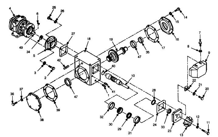
Install bearing cup (32), bearing (30), bearing
(29), and bearing cup (31) on quill shaft (10).
(7)
Install retaining ring (28).
(8)
Install new oil seal (33) in cover (23).
(9) Install cover (23), new gasket (24), and fan
brackets (22) on gear housing (18) using four screws (20)
and new lockwashers (21).
(10) Install new oil seal (34) in quill motor flange
5).
(11) Install quill motor flange (5) and new gasket
(27) on gear motor housing (18) using four screws (25) and
new lockwashers (26).
(12) Install shaft (19) in gear housing (18).
(13) Install new oil seal (35) in cover (16).
(14) Install cover (16) and new gasket (17) on gear
housing (18) using six screws (14) and new lockwashers
(15). Snug two of the screws and then check end play on
shaft (19). Adjust thickness of shim (17) until there is no
perceptible end play, then install and fully tighten screws
and lockwashers.
(15) Install fan (13) on quill shaft (10) using screw
(11) and new lockwasher (12).
(16) Install fan cover (9) on fan brackets (22) using
four screws (7) and flatwashers (8).
(17) Position gear housing (18) upright.
(18) Install key (6) in feed motor output shaft (49).
(19) Carefully position feed motor (4) for installa-
tion. Ensure that key (6) on feed motor output shaft (49)
properly engages keyway in quill shaft (10).
(20) Secure feed motor (4) to quill motor flange (5)
using four screws (2) and new lockwashers (3).
(21) Install feed motor and gearbox assembly (see
TM 5-3820-241-12).
(22) Service gearbox (see LO 5-3820-241-12).
14


