(i)
Hose bulkhead (see TM 5-3820-241-12).
(j) Control valves and manifold (see TM
5-3820-241-12).
(k) Impact valve and manifold (see TM
5-3820-241-12).
(2) Remove feedshell slide bars and cylinder
mount (see TM 5-3820-241-12). Once the slide bars and
cylinder mount have been removed, the feedshell can be
removed from the crawler.
b.
Repair. Refer to TM 9-237 for instructions on weld-
ing repair.
c. Installation.
(1)
Install feedshell along with slide bars and cylin-
der mount (see TM 5-3820-241-12).
(2)
Install the following components in the order
listed:
(a) Impact valve
and manifold (See TM
5-3820-241-12).
(b) Control valves and manifold (see TM
5-3820-241-12).
(c)
Hose bulkhead (see TM 5-3820-241-12).
(d) Foot (see TM 5-3820-241-12).
(e) Centralizer (see TM 5-3820-241-12).
(f)
Air motor and gearbox assembly (see TM
5-3820-241-12).
(g) Feed chain sprockets, bearings, and shafts
(see TM 5-3820-241-12).
(h) Chain adjuster (see TM 5-3820-241-12).
(i)
Feed chain (see paragraph 7-6).
(j)
Slabback (see TM 5-3820-241-12).
(k)
Drifter drill (see TM 5-3820-241-12).
(3)
Adjust chain tension (see TM 5-3820-241-12).
Section III. FEED AND LEVELING MECHANISM
7-5.
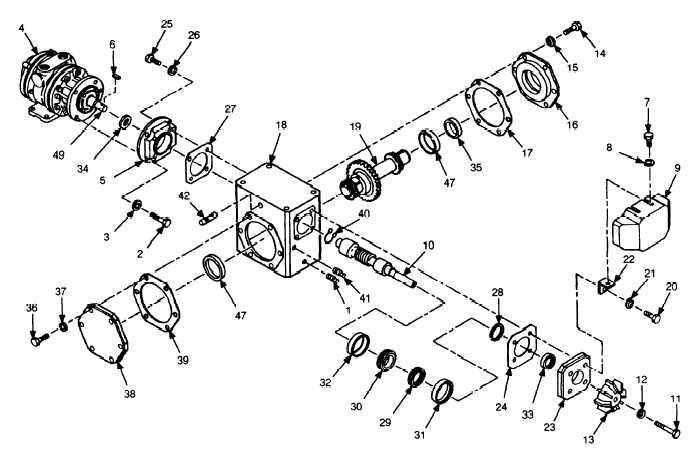
Gearbox Repair
a. Disassembly.
(2) Remove drain plug (1) and allow oil to drain.
Reinstall drain plug.
(1)
Remove feed motor and gearbox assembly (see
TM 5-3820-241-12).
12


